
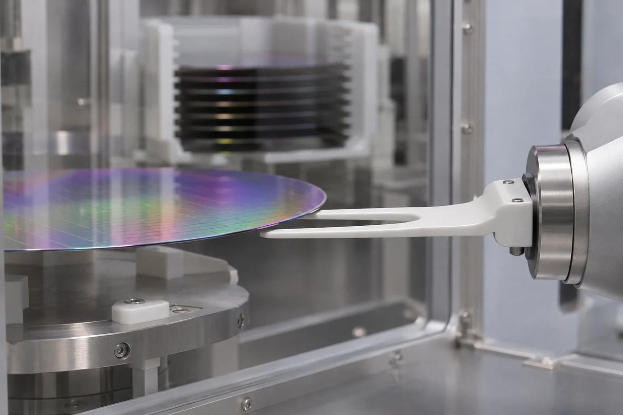
Start with the robot interface and the wafer contact scheme. A ceramic end effector needs to fit the tool, support or grip the wafer as specified, and operate within the station’s temperature, cleaning and contamination requirements. Document these inputs before asking for a grade or a tolerance.
What should be on the drawing?
Include the part number and revision, mounting datum, hole pattern, overall thickness, contact zones and allowable edge geometry. Identify the cassette or chamber clearances and the motion envelope at transfer. Include wafer diameter, backside contact restrictions, and any keep-out zones. For a replacement part, separate unworn interface dimensions from measurements taken on worn surfaces.
How should the material and grip be specified?
Alumina and silicon carbide are examples of ceramic materials used for wafer-handling arms. Compare a specific grade against the actual temperature cycle, cleaning media, stiffness and electrical requirements. Specify the support scheme explicitly. If the design uses vacuum, include the port, channel and pad geometry and agree on the pressure, fixture and method used to check leakage or holding performance.
What should the first article prove?
Agree which dimensions are critical, where and how they will be measured, and what the report will contain. Check the contact surface and edge condition, then validate fit, transfer motion and wafer contact in a representative fixture or tool. Add particle, cleaning and packaging checks where the process calls for them. Record the drawing revision, grade and sample identification with the results.
Prepare the RFQ
Share the drawing, mounting interface, wafer contact sketch and operating conditions for a feasibility review. For Malaysia-based equipment programs, use the regional enquiry page below.
Malaysia ceramic parts enquiry
For the wider equipment RFQ and first-sample checklist, see the Semiconductor Equipment Ceramic and Quartz Parts Procurement Guide.